
Advanced use and Definitions
Graphic Resources (3D)
In 3D a graphic resource is an element containing data about the render of a scene or an object.
These resources can be :
Mesh : It is the 3D model format, written as polygons or points defining its visual shape.
Material : It is the set of properties concerning the visual aspect of an object (reaction to light, color, appearance ...)
The photorealism of a 3D object is possible thanks to the use of texture
Texture : It is a set of 2D pixels that will be applied to a 3D surface or volume. By simplifying, one can assimilate it with a very plastic and deformable wallpaper that one applies in 3D by specifying the geometrical transformation that undergoes each pixel of the paper to apply on the element 3D. The pixel thus manipulated in 3D is called texel.
A texture can be defined analytically by an algorithm (procedural texture) or consist of an array of pixels (a bitmap image for example)
Resources groups
In the SCOL 3D engine, a resource group is a set of graphic resources allowing the integration of a group of objects into a scene.
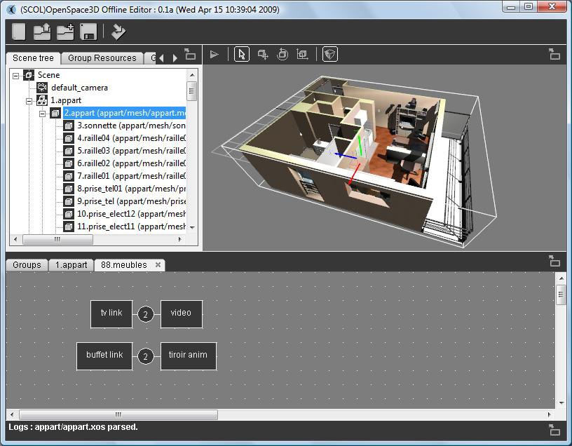
Here "1.appart" is a resources group containing all the graphic resources allowing the display of the apartment.
Mesh groups
Set of meshes constituting an object
Example :
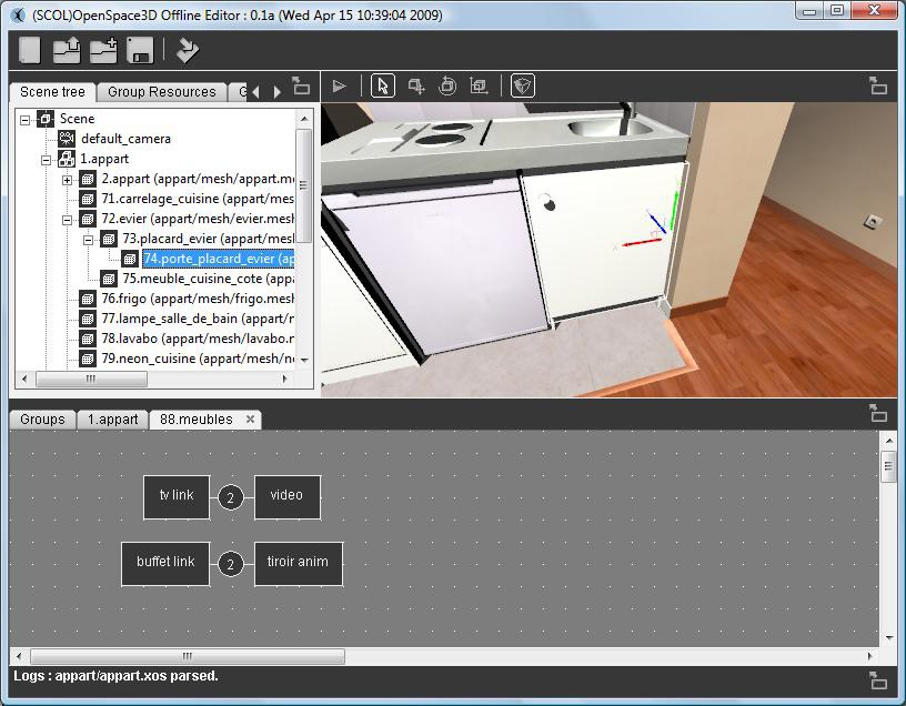
On this picture, "72.évier" is constituted of the meshes : "73.porte_placard_evier" , "74.porte_placard_evier" and "75.meuble_cuisine_cote".
Scene tree
A scene tree is a commonly used data structure of modern applications and computer games. The graphic scene is a structure that organizes the logic and spatial representation of the graphic scene.
A scene tree is a collection of nodes in a graph or structure tree. A node can have many children, but only one parent.
If a transformation is applied to the parent then it affects the entire hierarchy below it.
Example :
Scene node
A scene node is an element of the hierarchy of a scene tree; it can be a group, an object, a light, a camera, or the scene itself (the scene is the main node of the tree).
Dummy
It is an empty scene node, that is to say a reference in the 3D on which it is sometimes convenient to place other nodes in order to dynamically control the scene graph.
Group Resources
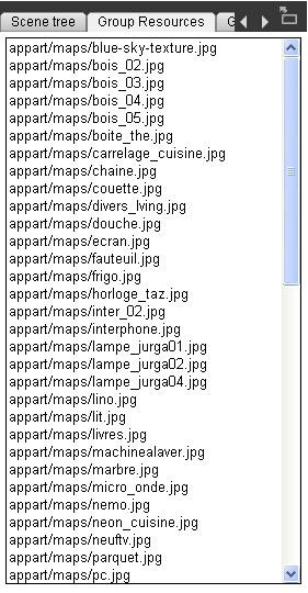
Here, the selected group in the Scene Tree is: ![]()
In the "Group Resources" tab you will find all its resources that can be manipulated.
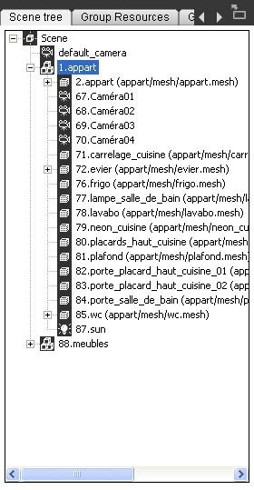
Group Meshes
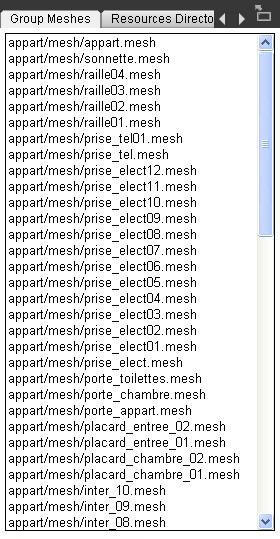
Here, the selected group in the Scene Tree is: ![]()
In the "Group Meshes" you will find all of its meshes.
Resources Directories
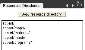
As previously explained, the 3D engine must know all the paths relative to the SCOL partition in order to be able to load the various resources necessary to display the different 3D objects composing the group in the scene.
Importing an Ogre resource (shaders, texture, material, mesh)
While building a 3D scene, you may want to import an object directly without going through an Ogre XML scene.
To do so, you need to know that Ogre Max allows you to export .mesh files and material resources (.material)
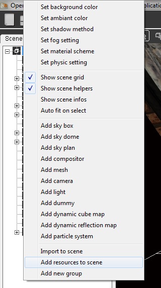
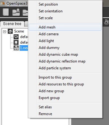
To import this data into the 3D scene or into a group go to the "scene tree" tab and right click on the scene or group in which you want to add the object. The procedure for adding a resource has several necessary steps that must be followed for the proper process of importing the object.
1 / The Ogre 3D engine needs to know where the resources to load are
Thus, in the tab "Resources Directories" it is necessary to add ALL the paths (relative to the partition SCOL) where will be the different graphic resources (.program, .material, textures ...)
2 / The next step is to add the graphics resources (.program and .material)
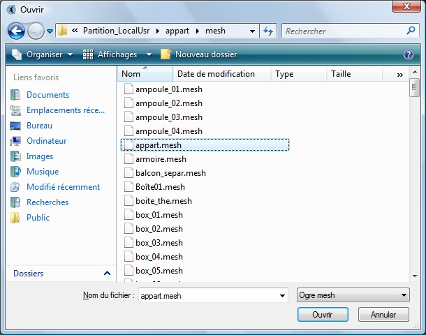
This tool opens the dialog window :
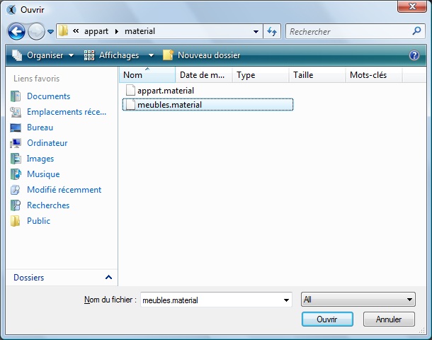
This is where we have to choose the different resources (.material, .program)
3 / The last step is to simply add the .mesh file corresponding to the object you wish to load into the scene or group
Since the graphic resources were previously loaded with steps 1 and 2, the 3D object will be displayed in the center of the scene with all its material, program and texture data.
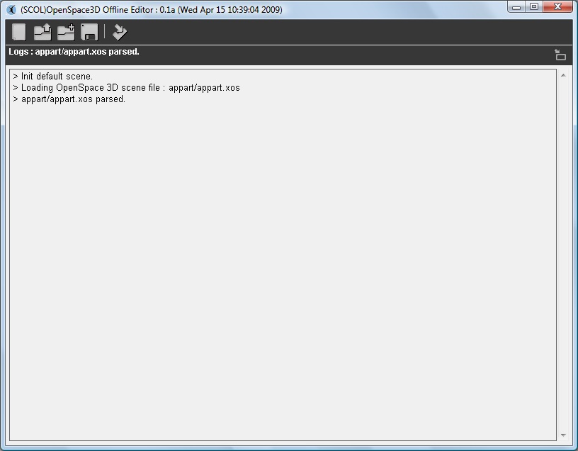
N.B : It is possible by displaying the log tab to see if no error message has been issued
N.B 2 : The "Group Resources" and "Mesh Resources" tabs make it possible to check if our resources have been loaded into the desired group.
Exporting a group
This feature is important when you want to develop a large project involving several people. Thus, it is possible to export a group that is to say the set of 3D objects and resources constituting it but also all PlugIT and features of this group.
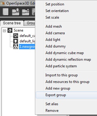
Thus, from another scene we can import the group directly by adding the .xos corresponding to this group. (see Import to Scene)
Definitions et advanced use of the parameters
- Light
In 3D, a light is used to illuminate the scene.
An ambient and unique light is set at the scene level (this is a bright overall intensity)
Then other types of lights exist and will have a different behavior on the rendering of the scene.
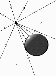
- Omnidirectional or point lights:
These lights are represented by a point that allows the light intensity to diffuse in all directions.
Their representation in the physical world may be the example of the light bulb.
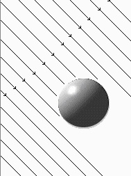
- Directional lights:
These lights are represented by a vector defining their direction, so a directional light is often assimilated to the sun because it corresponds to a light source located at infinity whose intensity reaches us with a given direction.
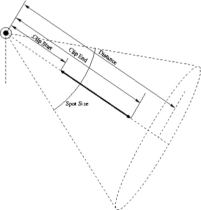
- Spot lights:
As their name suggests these lights can be likened to "Spot" bulbs.
Thus several parameters characterize them:
1 - Their opening or spot size which corresponds to a diffusion angle (the type of omnidirectional light is a special case of spots with a 360 ° opening)
2 - Their far clip or Range is the distance of illumination of the light. This value is used to define the distance from which the light no longer lights up.
Attenuation
Light attenuation in 3D is how the light intensity decreases with distance.
This data is defined according to the following formula:
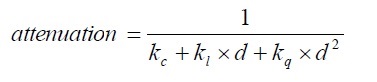
Avec d : distance à la lumière
kc : constant attenuation coefficient
kl : linear attenuation coefficient
kq : quadratic attenuation coefficient
Consequently, according to the variation of the distance the coefficients will be more or less influential (except for kc which is a constant attenuation which consequently defines the power of the luminous intensity)
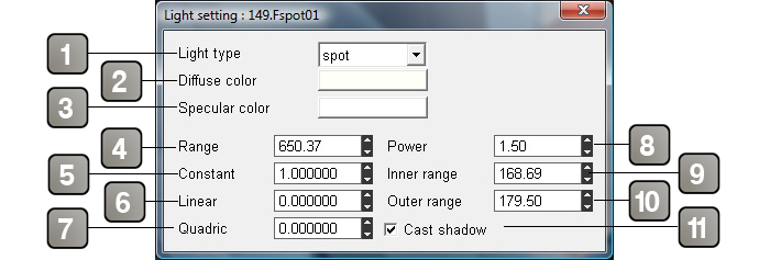
"Edit settings" of lights in the OpenSpace3D editor:
Parameters |
|
1 |
Type of the light |
2 |
Diffuse color. |
3 |
Specular color. |
4 |
Distance up to which the light illuminates. |
5 |
Coefficients of constant light attenuation. |
6 |
Coefficients of linear light attenuation. |
7 |
Coefficients quadratic light attenuation. |
8 |
power of the light. This variable is active only if the HDR is enabled on the scene. |
9 |
Spots inner range. |
10 |
Spots outer range. |
11 |
Enables / disables cast shadows. |
- Cameras
In 3D, a camera is a virtual representation of a real camera with parameters identical to a physical camera.
Thus, a 3D camera is the eye of the user allowing the observation and projection of the 3D world on a 2D plane representing the observed image.
The usual representation is called the "pin hole camera model"
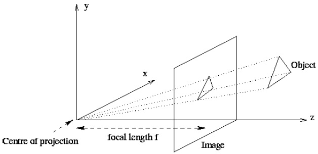
Focal length : The Focal distance of an object is defined by the measurement of its convergence power, it is related to the optical system because it defines the convergence power or divergence of the lens of the camera model.
Thus, the variation of the focal length causes a distortion of the 3D environment.
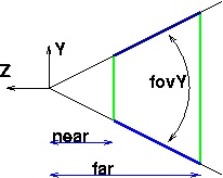
Near Clip and Far clip : These two parameters correspond to the area in which the camera will render (They define the frustrum)
If an object is beyond the far clip distance then it will not be rendered on the image.
Similarly, if an object is before the near clip distance it will not be rendered on the final image.
Fov Y: For Field Of View, which defines the angle of view of the camera as shown in the diagram above.
"Edit settings" of cameras in the OpenSpace3D editor:
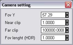
In the edit setting of the cameras, we find the various parameters to define the model of the camera used.
- Shadows
Shadows and shading are a particularly active area in 3D. Shading is at the heart of the realism of a 3D scene. Shadows result from an interaction between light and objects.
Depending on the environment and the type of light we will use one or another of the shadow projection techniques.
The main methods of shadowing are:
- Stencil Shadow Method
In the overall operation of Shadow volumes stencils, three actors intervene:
The lights
The Shadow-casters
The Shadow-receivers
Light is usually a positional light source or OMNI. The shadow caster is the object that cast a shadow on another object: it is the object that will block the light and create the shadow itself. The Shadow-receiver is an object that & quot; receives & quot; the shadow, or more precisely it is the object (all or part only) that is deprived of light.
The shadows are called volumic simply because the Shadow-caster will create a volume of shadow in which objects therein will not receive light.
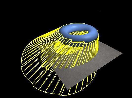
- Texture Shadow Method:
The principle is quite simple and natural. Indeed what makes that there is a shadow on an object?
The answer is obvious there is another object (or itself) that prevents light from waiting for the shaded part. In other words, there is a shadow on an area if there is another object closer to the light and which is on the path of the ray that should have illuminated our area.
The principle is therefore simple and very logical. At the pixel shader we will look if there is an object that is on the path of the ray of light and if it is then the area is shaded.
The basic algorithm will therefore be done in two steps.
The first is to render the scene in a texture (render target) taking the light as a camera. If you have several lights, you have to do it for each of them. When we surrender we will only store output of which we need to know the depth.
In the case of an omnidirectional light, all this is complicated, it is necessary to go through a cube map to have the depth of all that is illuminated by the light.
The second step is to display the scene normally and take care of the pixel shader shadow.
The pixel shader needs the coordinates of the point in the light guide. We then have all it takes to know if the current pixel is shaded or not. Indeed if the depth in the depth texture at the coordinates of the current pixel is smaller than that (in the light reference) of the current pixel then the pixel is shaded.
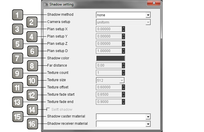
"Edit settings" of shadows in the OpenSpace3D editor:
Parameters |
|
1 |
Allows to choose the type of technique of the method of shadows (stencil or texture) |
2 |
Option for the case of Shadow textures, allowing an optimization of the computation of the shades as well as a greater efficiency of the computation of shadow. |
3 |
Optimization plan X |
4 |
Optimization plan Y |
5 |
Optimization plan Z |
6 |
Optimization plan D |
7 |
Sets the color of the projected shadows. |
8 |
Allows you to define a distance from which the objects will not project shadows (camera / object distance). This makes it possible to optimize the scenes by not making a projection calculation beyond a given distance. |
9 |
Allows you to define the number of Shadow texture that will be used |
10 |
Sets the resolution of the texture of shadows so the resolution of the quality of the shadows. |
11 |
Sets an offset on the render (an offset is an offset of the shadow texture) |
12/13 |
These parameters will set the fading of the shadow on the edges from the Start fade to the End fade or the projection will stop. |
14 |
Enable auto shading. |
15 |
|
16 |
|
N.B : Depending on the type of light in the scene, the quality of the shadows will be better or better. For example, Shadow stencils work very well with directional lights, while shadow textures will react well to omnidirectional or spot lights.
N.B 2 : You can not define multiple shadow methods for a scene
- SkyBoxes and scene environments
The scene files loaded into openSpace 3d, exported via Ogre Max are XML files containing the definition tags for objects, groups of objects, but also environment variables.
These environments define, for example, the type of shadow method in the scene or the Fog parameters, the background color ...
Anything that refers to the scene directly.
Thus, skies or skies are also of these variables.
There are 3 types of Skies in Ogre:
- SkyBoxes: For this type of Sky, the sky is represented in the form of a box encompassing the scene
- SkyDomes: For this type of Sky, the sky is represented by a dome
- SkyPlanes: For this type of sky, the sky is represented by a plane located above the 3d scene.
The Physics engine
- The Newton physics engine
The physics engine used by OpenSpace3D is the Newton engine.
![]()
A quick description of this engine is available on Wikipedia :
https://en.wikipedia.org/wiki/Newton_Game_Dynamics
Partial integration
The integration of the Newton physics engine into OpenSpace3D has only been partially completed. More advanced features will come in an upcoming version of OpenSpace3D.
However, currently OpenSpace3D manages the fundamental bases to make realistic physics on developed environments.
Reminder and Definitions:
World: It corresponds to the physical world associated with a scene (it has a size and basic options such as the gravitational constant)
Body: Physical envelope applied to an object to optimize the collision calculation
Shape: Optimized Physical Envelope for Complex Objects
Collision Tree: Exact collision envelope on objects considered static (no forces) but sensitive to collision (ex: Walls of a house, ground ..)
Architecture model: Level of precision of the model that will be used by the physics engine for the calculation of the simulation
Solver model: Level of precision for calculating the result of the application of physical force on an object
Friction model: Level of precision for the calculation of the result relative to friction between objects.
FrameRate: Fast update of physical phenomena.
Physic material: Physical materials associated with a body. Ex: wood, iron ...
Angular Damping: Concept relating to the center of gravity of an object.
Contact: Phenomenon occurring when two objects (associated with physical materials) collide with each other.
N.B: The reaction values (elasticity, softness, friction ...) at the collision of two bodies correspond to the resultants of the contact between two physical materials.
Elasicity: Coefficient of elasticity between two materials.
Softness: Coefficient corresponding to the damping of the contact.
Thickness: Coefficient corresponding to the thickness of the contact.
Static friction: Coefficient of static friction
Kinetic friction: Coefficient of dynamic friction that is to say dependent on the speed of objects at the moment of contact.
The physics parameters in OpenSpace3D
At scene level :
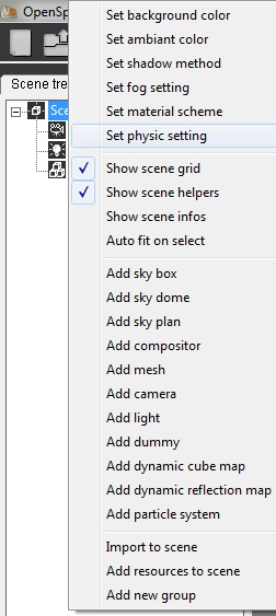
By right clicking on the scene (in the Tree scene) we access the general configurations of physics at the stage level
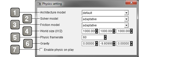
Parameters |
|
1/2/3 |
Physics engine calculation options (see Reminders and Definitions) |
1 |
Architecture model |
2 |
Solution model |
3 |
Friction model |
4 |
Size of the physics world |
5 |
Physics refresh rate |
6 |
Value of the gravitational constant (on Earth: 9.81) |
7 |
Activation of physics in the application. |
At objects level :
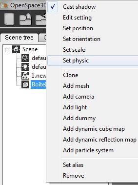
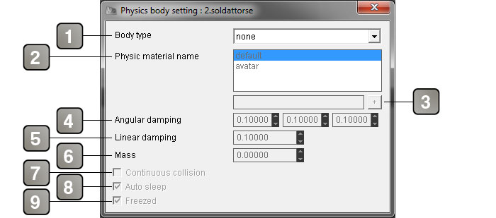
By right clicking an object of the scene tree: (set Physic) we access to the physical configuration of an object:
Parameters |
|
1 |
Body type applied to the object |
2 |
Management of physical materials: we choose either by the drop-down menu of the materials present in the scene or by a direct addition by the name on which physical material we apply our object |
3 |
Allows to add a new physics material |
4/5 |
Initial values of the physics on the object: Damping (see Reminders and Definitions) |
4 |
Angular damping |
5 |
Linear damping |
6 |
Object mass in kg |
7 |
Continuous collision |
8 |
Enables / disables the recognition of the object when it finds a balance. (Force physics) |
9 |
If checked, wait for a contact before applying physics. |